¶ Introduction
You will find here the documentation for the visualization tools of the interface: the Workspace and the 3D Viewer.
From the Workspace, you can quickly have a look at your structures in the 3decision visualization panel, the 3D Viewer, and perform on-the-fly superposition, measurements, and other actions.
¶ Access
You can access the Workspace by two ways:
- from the Search results page, if you click on the "OPEN" action button (on the top right of the page) you will be automatically redirected to the Workspace.

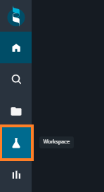
- You can go back to the Workspace from anywhere in 3decision, by clicking on the lateral bar "flask button" (on the left of the screen).
¶ Workspace
The Workspace layout simplifies the visualization and comparison of protein structures. It allows the user to collect, overlay and analyze structures coming from different sources in a single place.
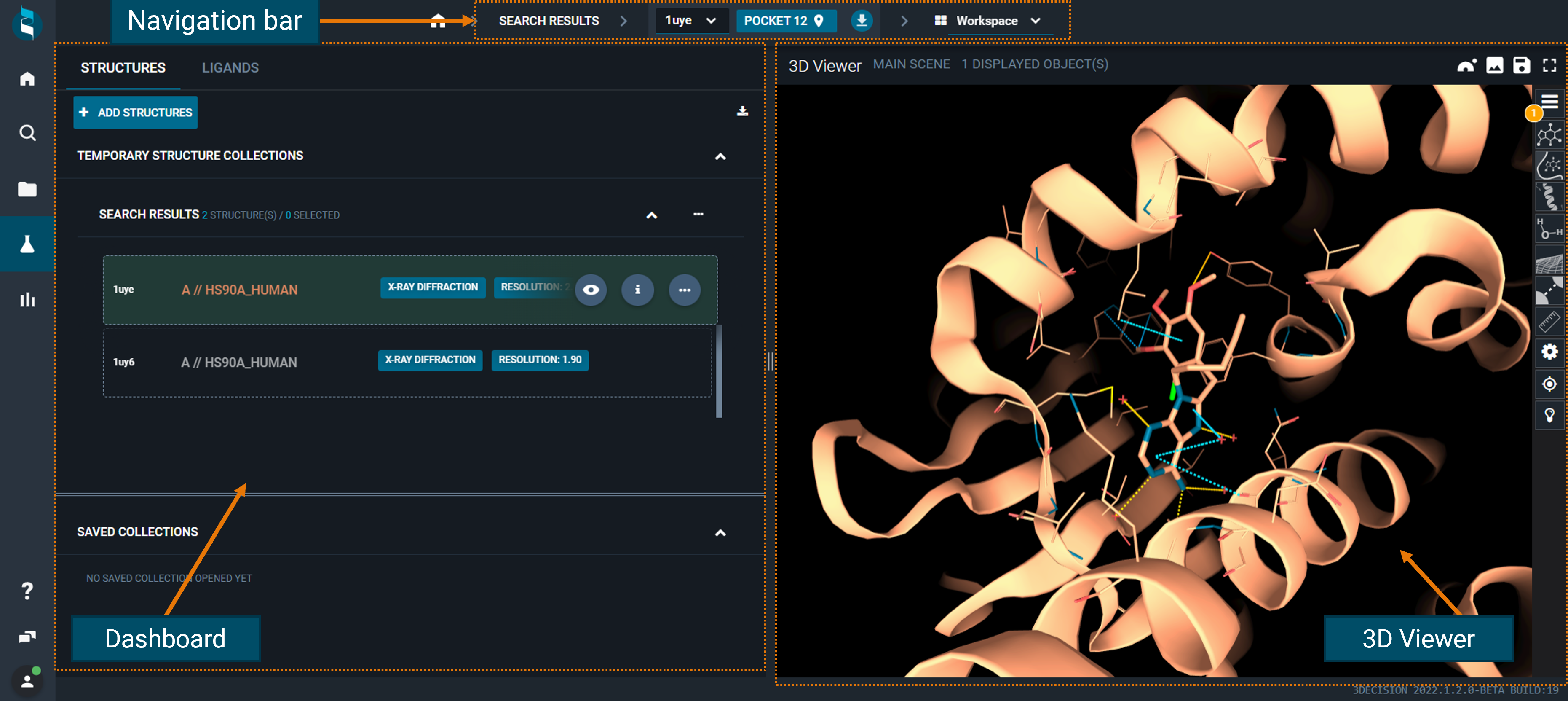
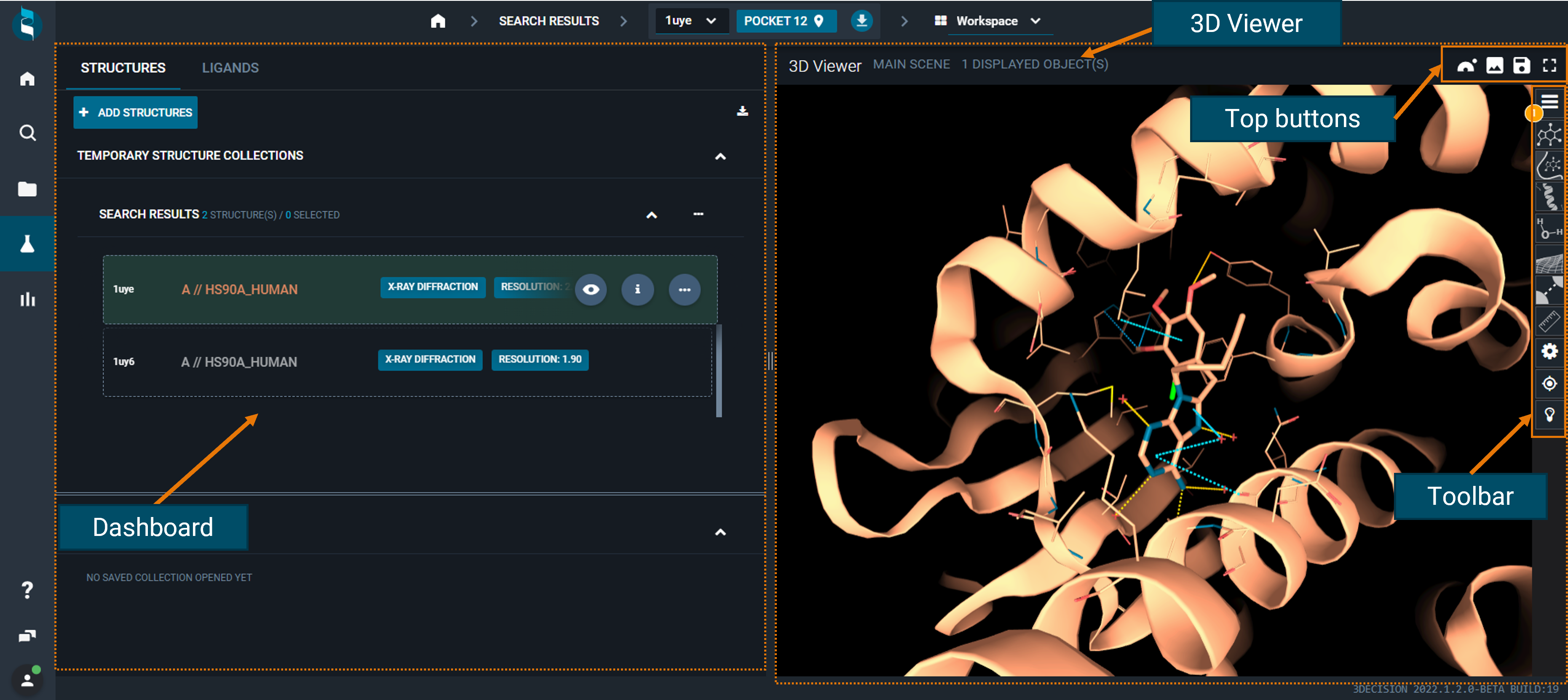
The Workspace is divided into three sections:
- on the left, there is the dashboard, which allows you to manage the structures and perform some actions
- on the right, there is the 3D Viewer, for visualizing the 3D protein structures
- on top, there is a navigation bar, to change reference structure/pocket and switch to other layouts:
¶ Navigation bar
From here you can see the reference structure (and the reference pocket) of your current workspace, and change the layout by using the drop-down menu.
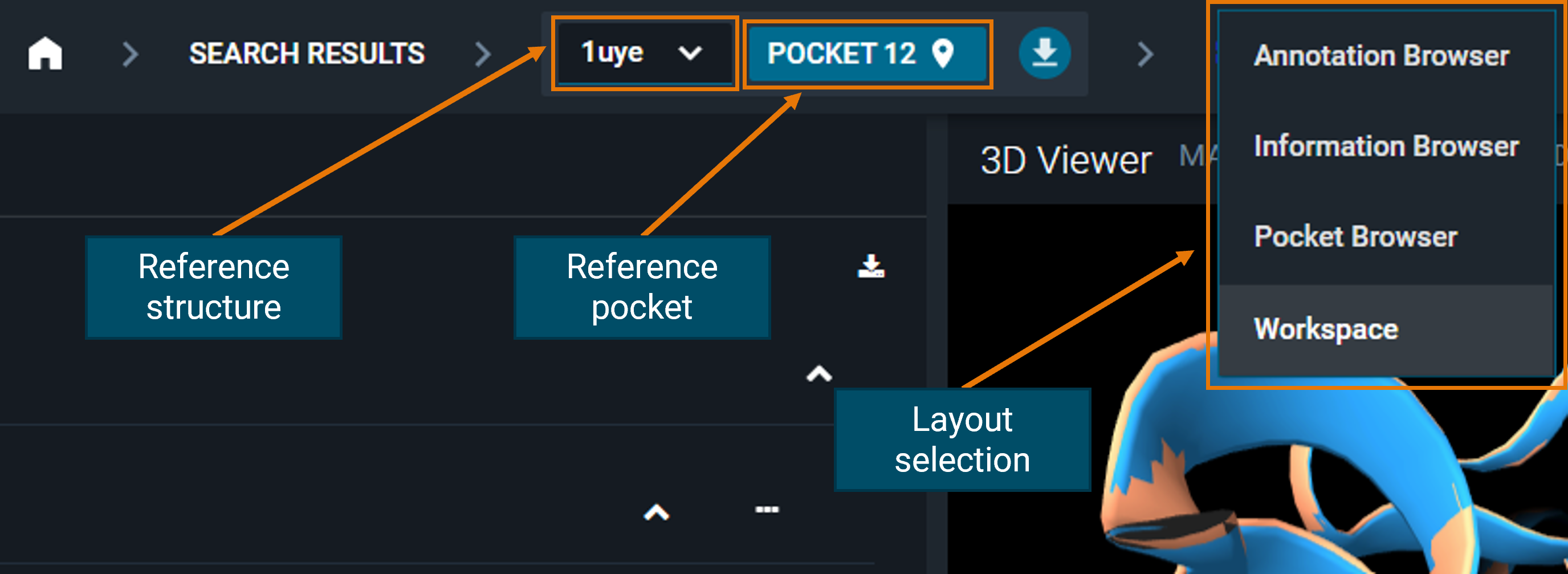
If you have more than one structure loaded in the workspace, the other layouts (Annotation, Information, and Pocket Browser) will show only information on the reference structure, not on all the loaded structures. Even if you navigate through the different layouts of the reference structure, you will not lose the other structures loaded in the workspace.
¶ Reference Structure
By default, the reference structure in the Workspace is the first one to be added.
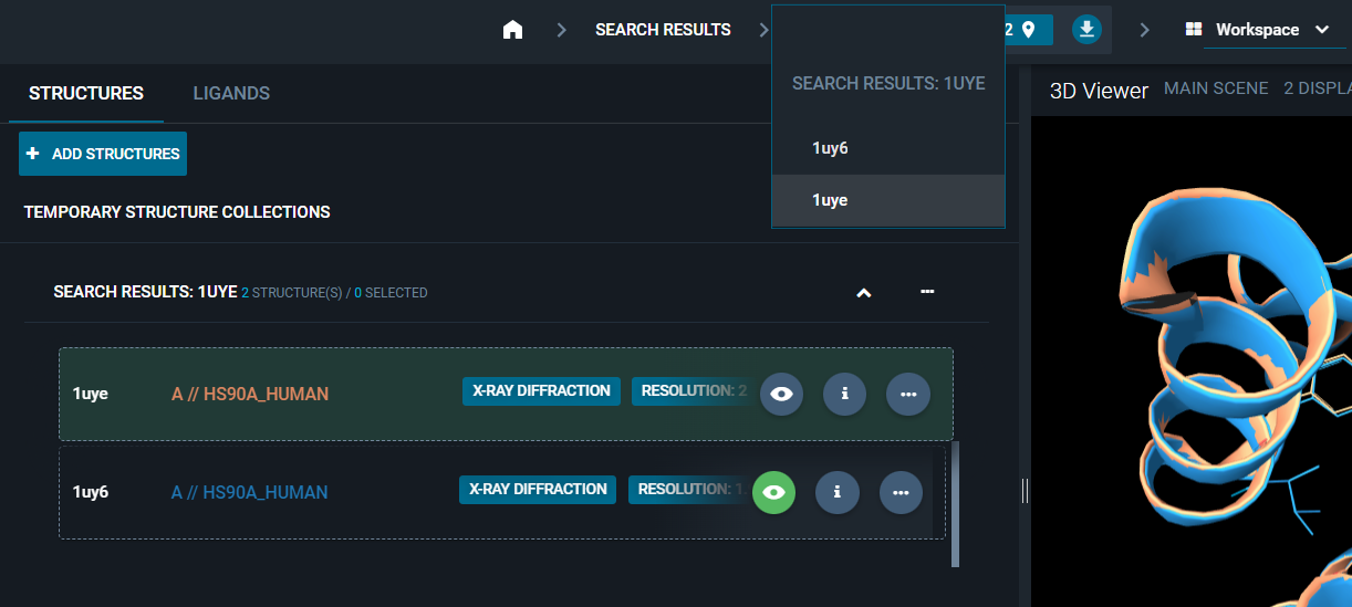
If you want to change the reference structure of your workspace, you can do it by clicking on the reference structure code in the navigation bar: a list of all the structures loaded in the workspace will appear. Just click on the code of the new reference you want to set.
¶ Reference Pocket
The reference pocket is the one with the bigger druggability score and/or in complex with the biggest ligand. The reference pocket is very important in 3decision, since the on-the-fly superposition is pocket-based (see more details on this in the following section of this page: Superposition).
You can change the reference pocket of the reference structure in two ways:
- Click on the reference pocket in the navigation bar at the top of the screen and a pop-up with the list of pockets in the structure will appear. Click on the pocket you want as new reference and close the pop-up. It will now be set as the reference pocket.
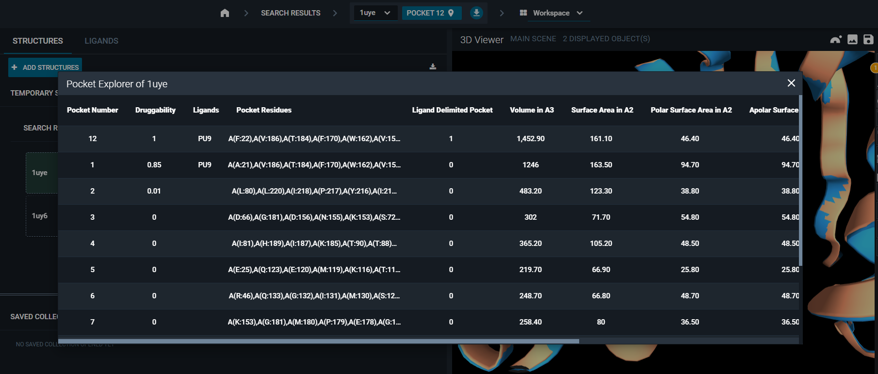
2. Use the Pocket Browser layout. Click on a pocket in the list and it will be automatically set as the reference pocket of the workspace.
¶ Dashboard
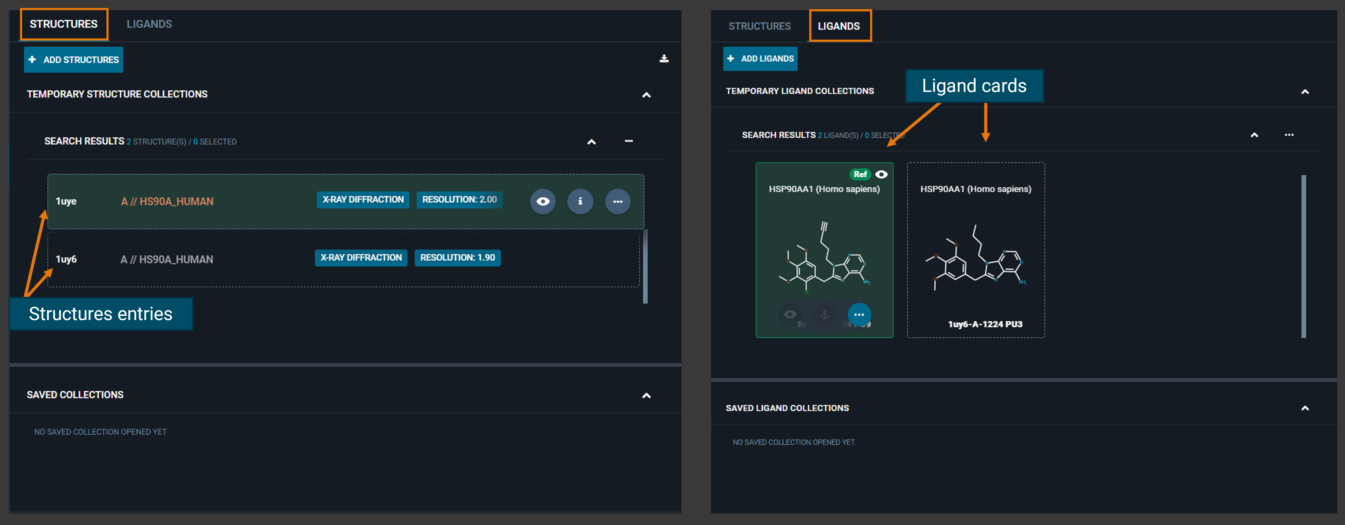
From the top-left of the dashboard, you can switch between two tabs (STRUCTURES and LIGANDS) that allow you to perform different actions.
The structures that you open from the search results page, are listed in the STRUCTURES tab, while in the LIGANDS tab are collected all the ligands (as cards) detected in the loaded structures.
¶ Structures Tab
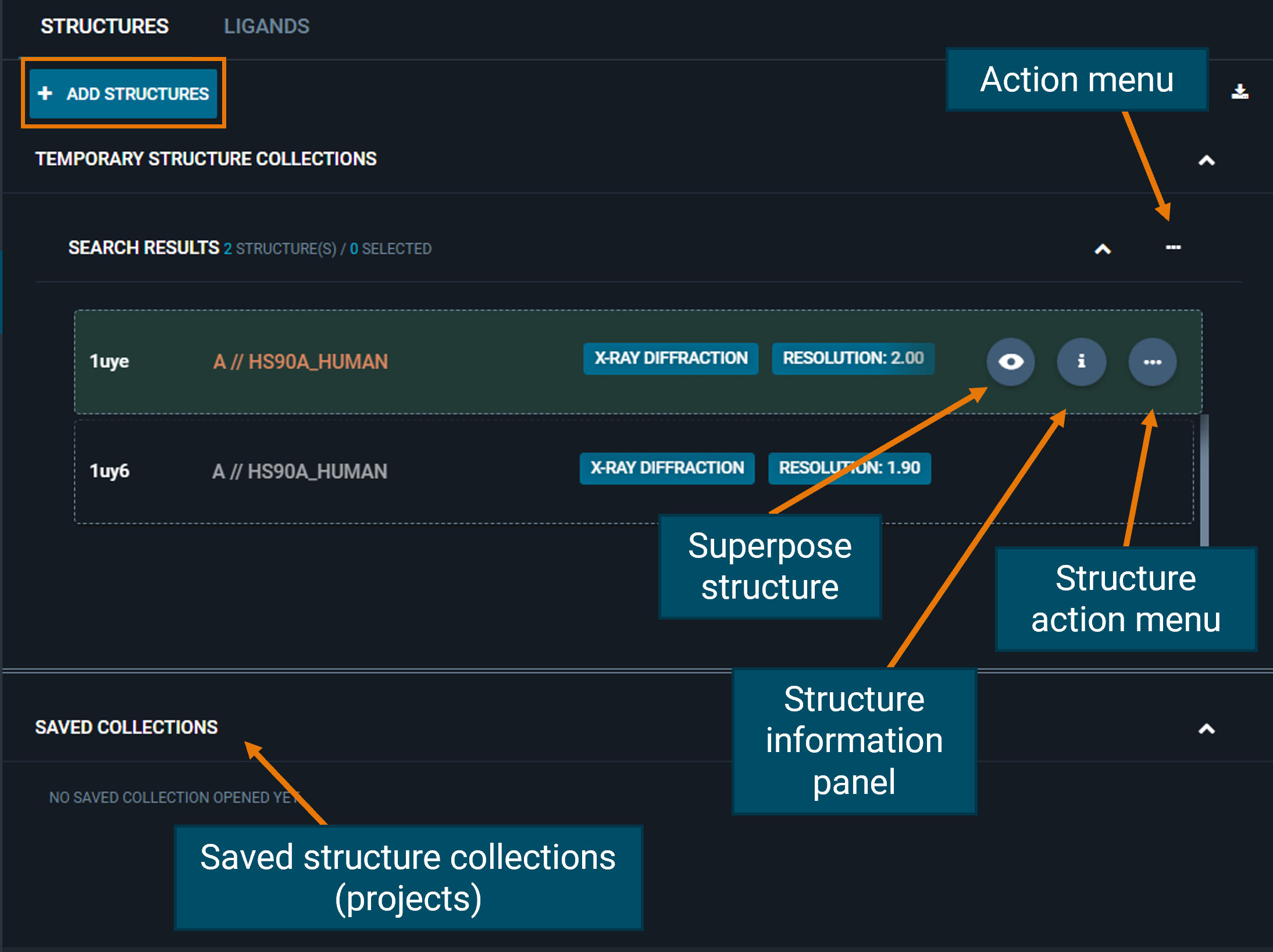
From the STRUCTURES tab, you can add more structures to the workspace directly from their structure codes using the blue ADD STRUCTURES button.
You can perform actions on the whole group of structures that are loaded in the workspace from the three-dot "Action menu"; for instance, you can add all/selected structures to a project, download or superpose them.
Also, you can perform actions on a single structure: on the right, there are three buttons (fixed for structures opened in the 3D Viewer, or hidden if not) for:
- on-the-fly superposition of structures (eye button)
- access the Information panel (
ibutton) - open the structure action menu (three-dot button)
From the structure action menu you can change the selected pocket, fetch Electron Density maps or calculate Protein-Protein Interactions.
¶ Ligands Tab
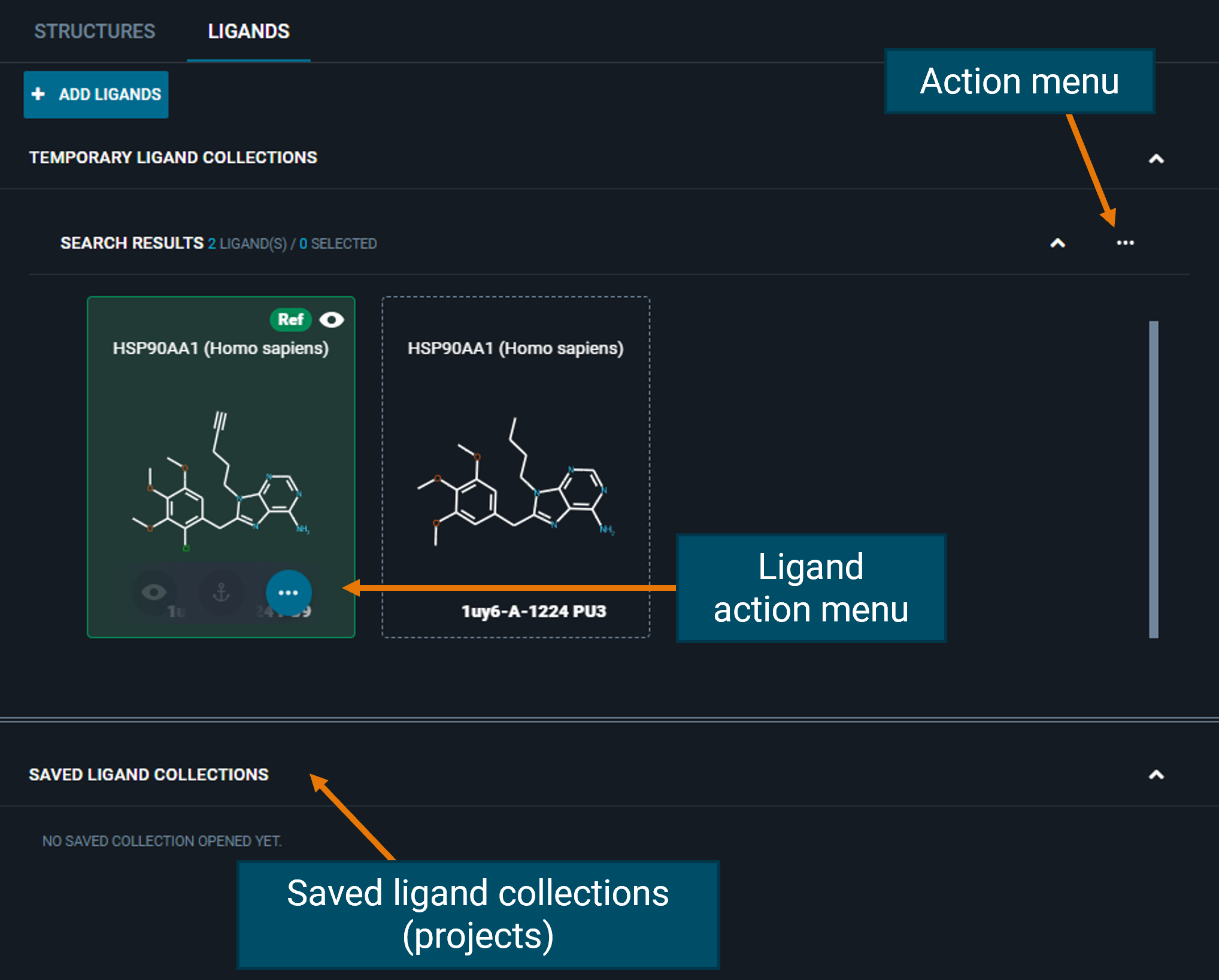
From the LIGANDS tab, you can perform actions on all ligands from the "Actions menu" on the top-right fo the collection, or on the single ligand from the three-dot button on the ligand card. From the Ligand action menu, you can run Chemistry Search (see specific section in Search).
¶ Superposition
By default, when loading multiple structures in the Workspace, only the first one is automatically opened and displayed in the 3D Viewer. If you want to add a second structure to the view, just press the eye button and in one click you will have your structures superposed.
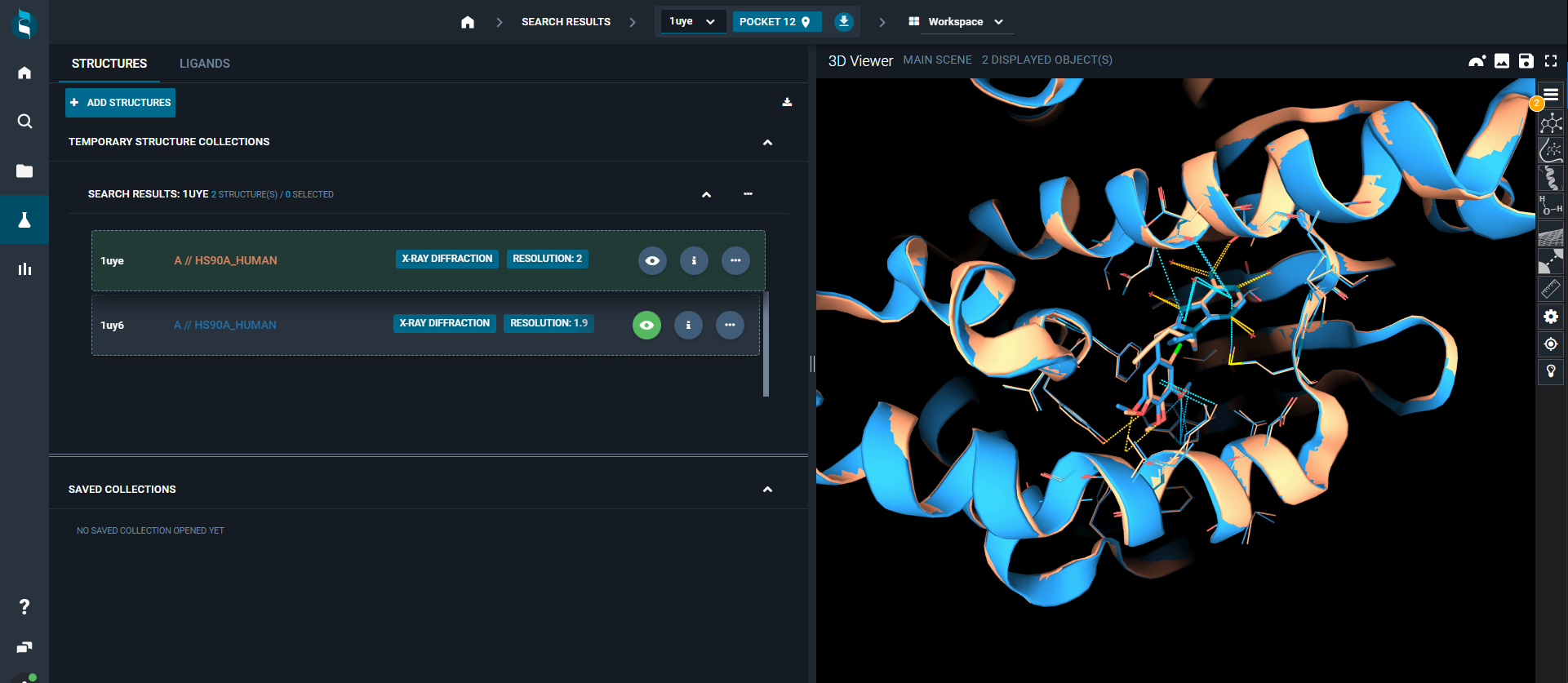
The on-the-fly superposition in 3decision is pocket-based:
- By default for each structure, the reference pocket is the one with the bigger druggability score and/or in complex with the biggest ligand
- If the two structures are containing the same biomolecule (i.e protein), the binding site residues are selected on both structures and a distance weighted optimization is run to superpose the two structures
- If the two structures are not containing the same biomolecule, the first step is to identify the best matching pocket. To do that, a sequence alignment of all biomolecules composing the reference pocket versus all biomolecules in the structure to superpose is run. The best matching alignment is kept. Then on this identified biomolecule the pocket overlapping the most with the pocket aligned on the reference structure is selected. From this, the residue mapping allowing the distance-weighteded superposition is extracted
- If these two possibilities do not work (no homology), no superposition is possible but you can choose to do a manual superposition (selecting the two corresponding chains to superpose) thanks to a pop-up windows that will appear
¶ 3D Viewer
The 3D Viewer is an interactive visualization tool:
- all the actions performed on the dashboard will be immediately displayed in the 3D structure
- the view can be personalized and adjusted with some buttons in the toolbar on the right
- you can perform additional actions using the top buttons
¶ How to use the mouse
Here are the mouse controls for the 3D Viewer, for a classic "wheel" mouse.

¶ Top buttons
Above the 3D Viewer, you have four aligned buttons that allow you to:
- Open the visualized structure in Nanome
- Save the view as a .png file
- Open save options (save picture; save scene; save scene as...)
- Switch to full screen
¶ Toolbar (right-side buttons)
On the right on the 3D Viewer, there is a lateral toolbar, with many shortcuts to customize the scene, and to perform some measurements and on-the-fly analyses.
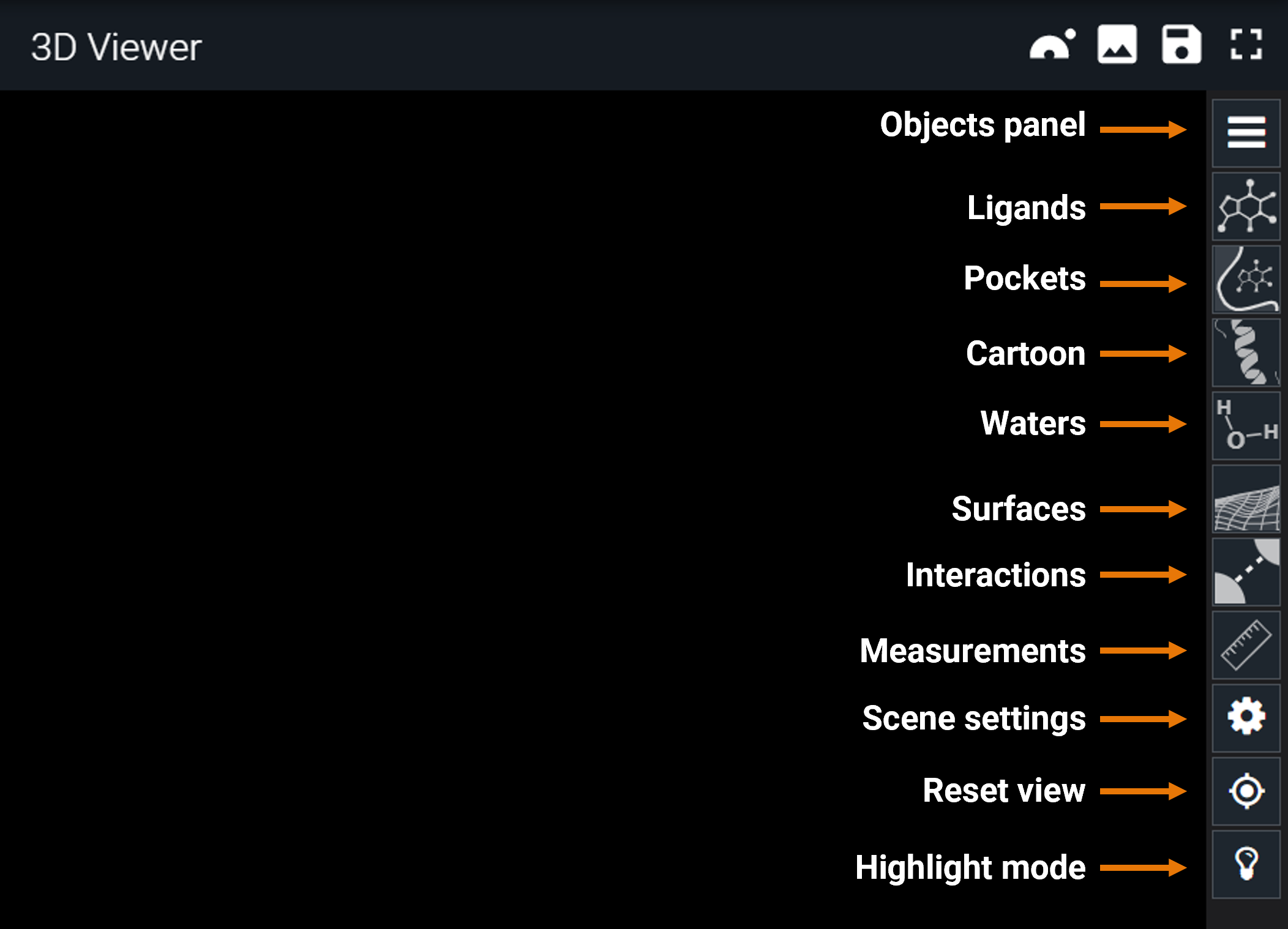
In the following sections, the specific use of each of the buttons of the toolbar are described.
¶ Objects panel
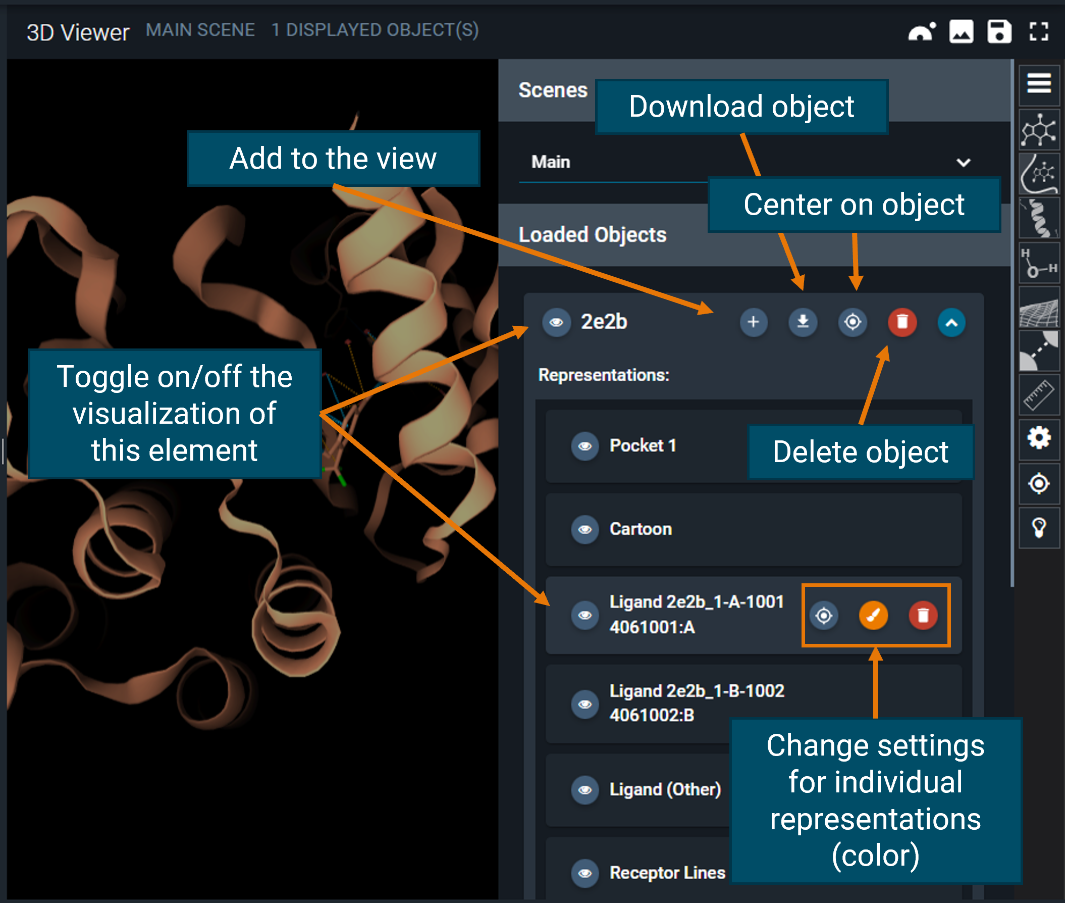
From the top of the toolbar, the first button is the "hamburger button", which opens the objects panel. Here, you will find one line for each structure you added to the 3D Viewer (from the dashboard).
You can finally customize the view of each of the loaded structures using this panel, for instance changing the color or toggling on/off the visualization of certain objects.
¶ Representation options
¶ Ligands/Pockets/Cartoon/Water
In the toolbar there are some shortcuts to hide/show in one click, all ligands/pockets/cartoon/waters of the objects present in the 3D Viewer.
¶ Surfaces
You can add surfaces to the dislayed structure(s) from the Surfaces menu, which opens clicking on the surfaces button.
You can choose to which object adding the surface (pocket, ligands or biomolecule) and which type of surface (solvent accessible surface, Van der Waals surface, etc.). Also, you can pick if adding a solid or meshed surface and modify the opacity.
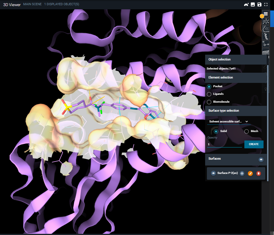
Once the surface is created, it is added both to the objects panel and to the surfaces menu. From both, you can customize the surface color using the brush button or delete it. Legends for coloring scheme by b-factor and hydrophobicity can be found here: https://www.rcsb.org/docs/3d-viewers/mol*/managing-the-display#set-coloring.
¶ Scene settings
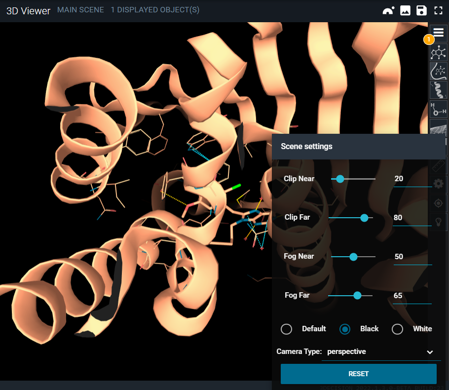
You can adjust the clipping and the fog of the 3D Viewer by the Scene settings menu (gear button).
¶ Reset view
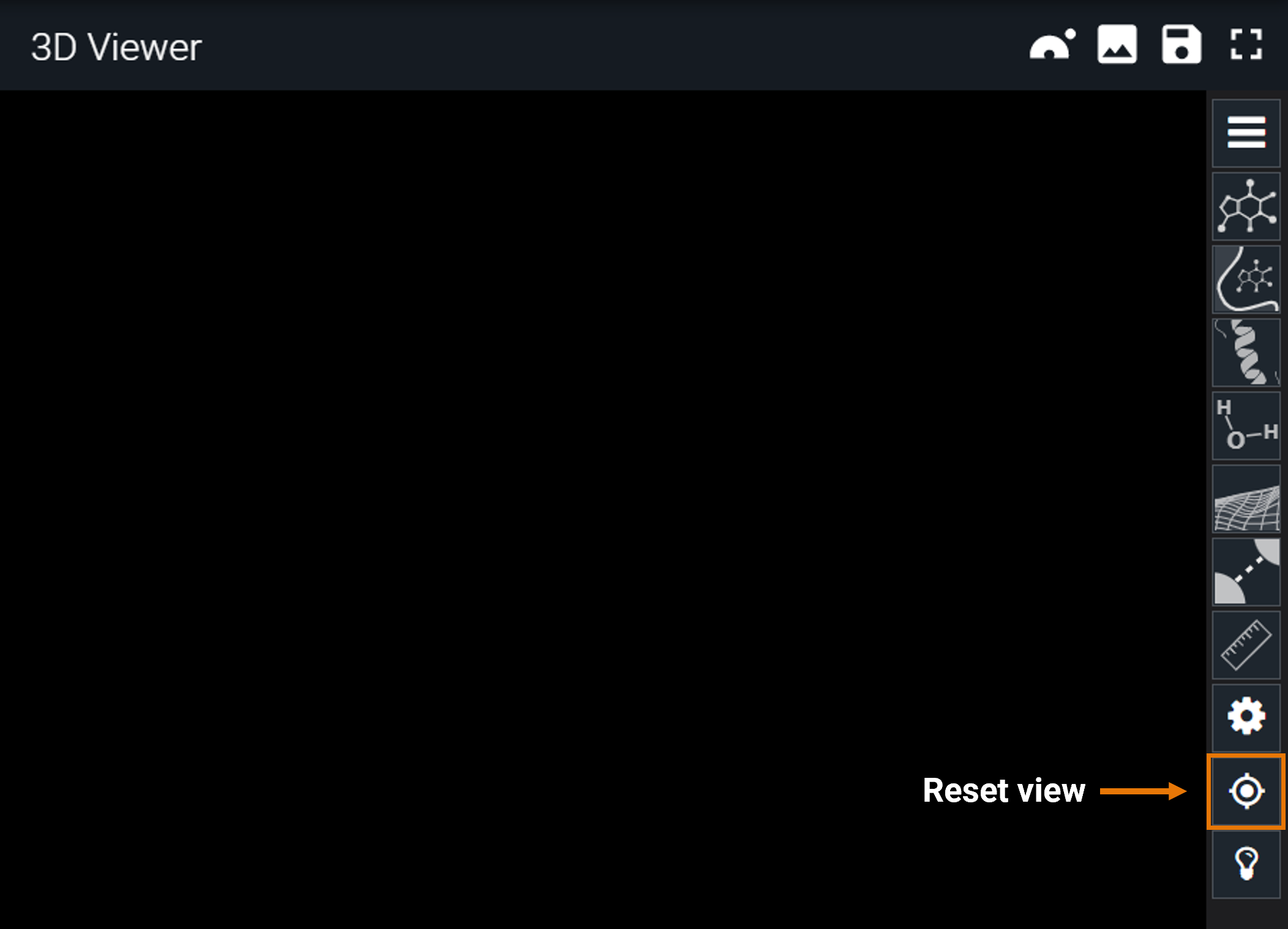
If you get lost in the 3D structure, you can always restore the original viewpoint by clicking on the "target" button.
¶ 3D Viewer analysis tools
¶ Interactions
In 3decision, the ligand-protein interactions are automatically calculated upon registration of the protein structure in the database.
Since version 2022.1.2, 3decision can also detect protein-protein interactions PPI on-the-fly. You can know more in the dedicated page PPI.
¶ Ligand-protein interactions
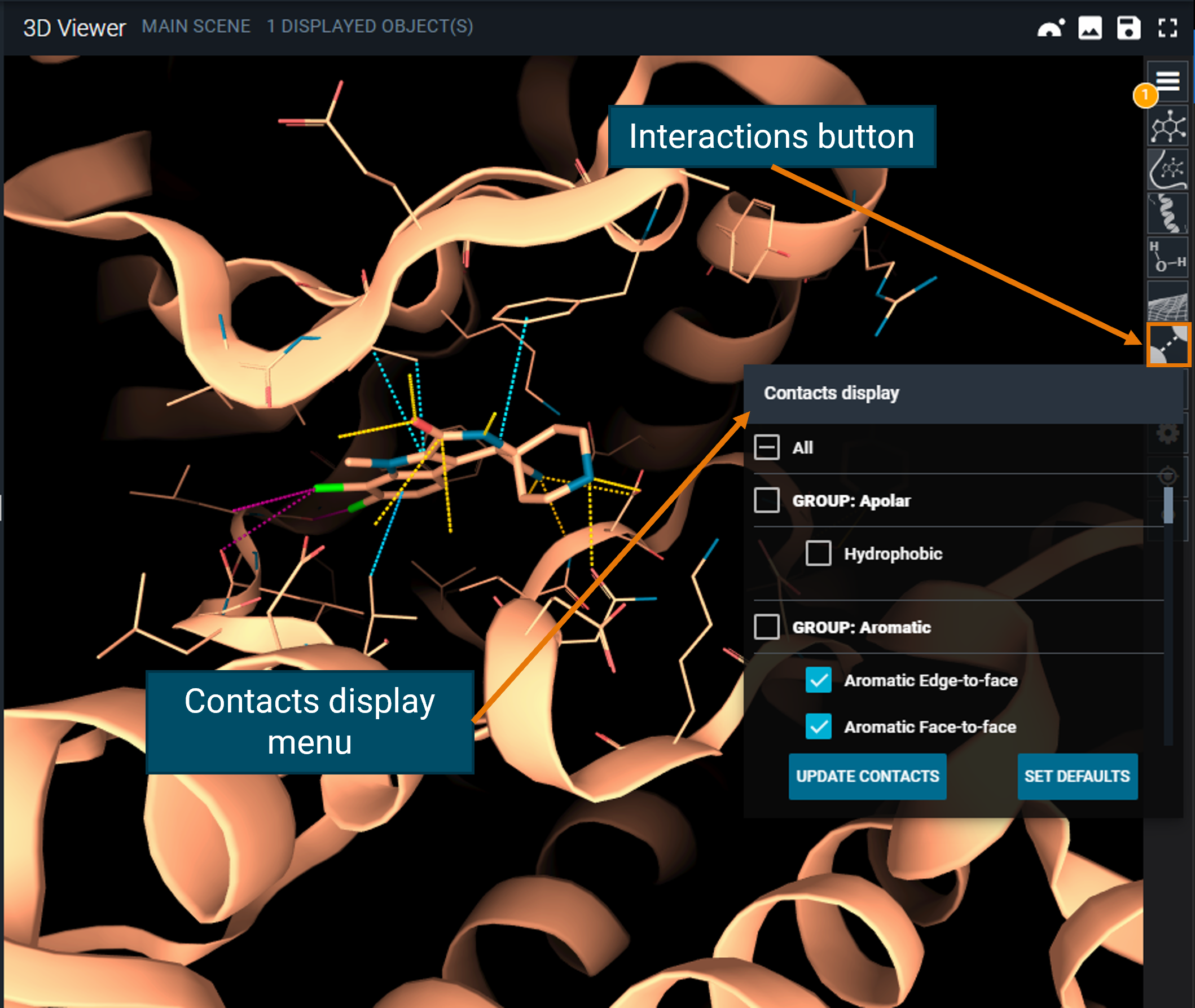
Ligand-protein interactions are represented by dashed lines, color-coded by interaction type :
- yellow for polar and electrostatic
- green for hydrophobic
- light blue for aromatic
- pink for halogen bonds
You can get more details on each displayed interaction by hovering with the mouse on it: a label describing the type and distance will appear.
Details on interaction types can be found in Interaction Search documentation, but here is a summary of the interactions computed by 3decision:
- Apolar (hydrophobic)
- Aromatic (edge-to-face; face-to-face; sandwich; side-by-side; etc...)
- Electrostatic (ionic; potential ionic)
- Polar (amide interaction; H-bond; halogen bond; polar interaction; etc...)
- Suboptimal contacts (critical clash; light clash; ionic repuslion; etc...)
Contacts not typed will be regaistered in database as Uncharacterized, in order to allow their selection for use as input in InteractionSearch feature.
You can toggle the visualization of the interactions you are interested in by using the Contacts display menu, accessible from the toolbar (interactions button) and then clicking on the UPDATE CONTACTS button. You can always go back to the default interactions by clicking on the SET DEFAULTS button.
¶ Measurements
In the 3D Viewer you can quickly calculate distances, angles and dihedrals using the measurement options. Access the menu by clicking on the ruler button from the toolbar. From here, you can select the type of measurement you want to start (distance, angle, or dihedral).
For instance, if you want to measure the distance between two atoms, select the option "distance" from the measurement menu, and then click on the atoms. 3decision will display a dashed line connecting the atoms and the result of the measurement. After you are done with all the measures, click on QUIT (on the top left) to exit the measurement modality, or click on the ruler button of the toolbar and toggle the Off option.
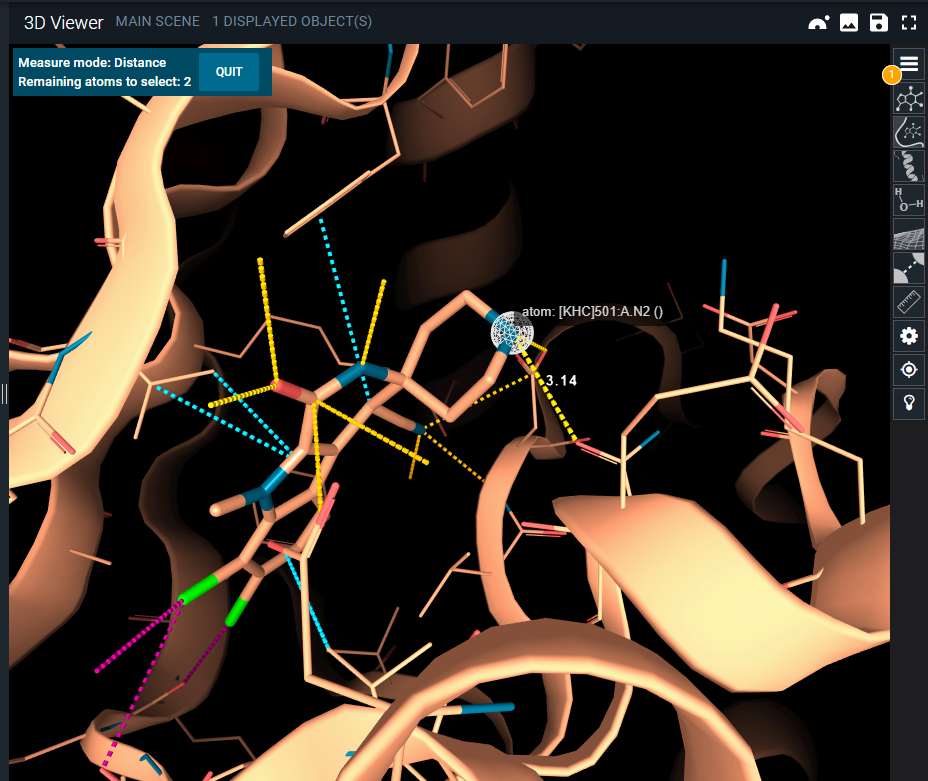
Keep in mind that when you perform a measurement, it is registered as a new object in the objects panel. From there, you can hide/delete the measurement if you do not need it anymore.
¶ Highlight Mode
The 3D Viewer Highlight Mode was introduced in 3decision with the aim of simplifying the view when several structures are superposed.
Usually, the aim of superposing structures is to identify common and differing structural motifs. With this new mode, the representations for each structure are altered to display only those parts that are different between the structures in the scene. Alternatively, if you need to see the common parts, you can toggle the "show common parts" option and the behavior is inverted.
The light bulb icon on the toolbar opens the Highlight Mode menu. There are two different modes:
- Full Structure
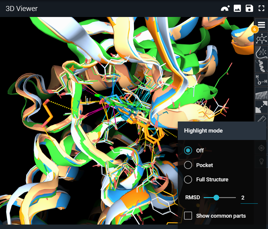
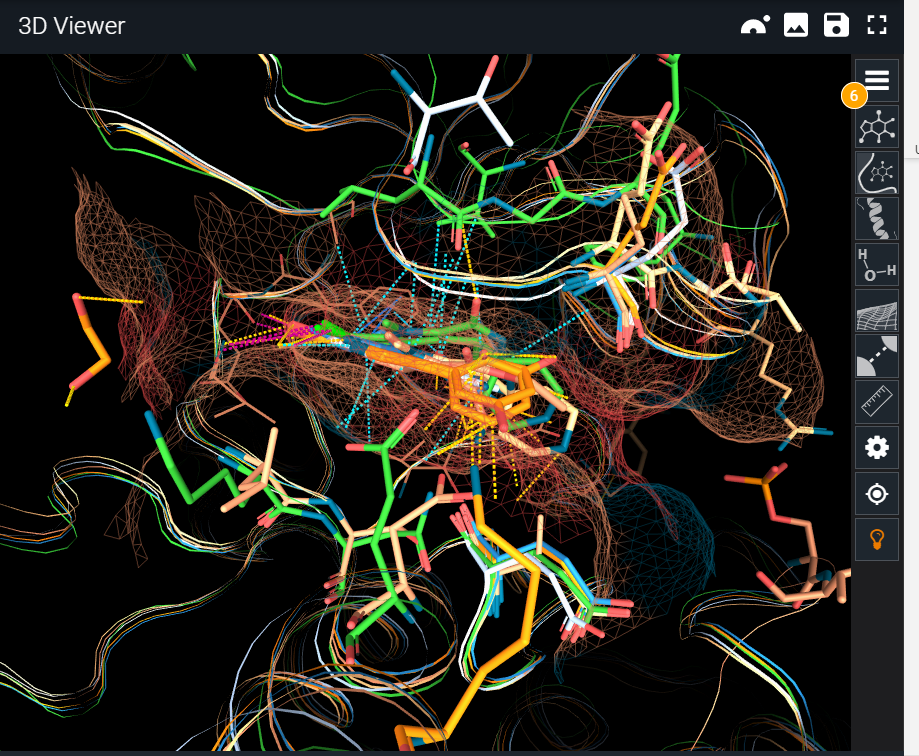
Pocket mode focuses on the binding site. This mode is useful when studying binding site differences across targets and off-targets or comparing different conformations of the same target.
It will display differences within the binding site residues. It will display in sticks only the residues that are different to the reference structure and will not display anything for the common residues. A backbone representation and the surface of the reference binding site are added by default to the view. The reference will be the first object in the scene.
¶ Full Structure
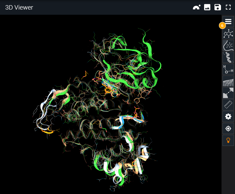
Instead of comparing only the binding site, in this mode we extend the representation to the whole protein structure, to study conformational changes. Keep in mind that the alignment is still made over the binding site. In this case, the binding site surface is omitted and differences are displayed all over the structure.
¶ RMSD Slider
The RMSD slider allows you to control what is considered as different in terms of conformation. At lower RMSD, even residues with only slight conformational shifts will be detected as different and displayed.
The “Show common parts” checkbox will inverse the behavior and will display common features instead of the differences, always using the same representation mechanism.
¶ How does 3decision decide if a residue is a difference or not?
It goes through two steps: matching and difference assessment.
-
Residue matching:
In order to decide if two residues are a match to be compared against each other, only the carbon alpha positions of the amino acids are checked. If they are close in space, they will be considered as matching. Therefore, the alignment/superposition of the structures is the first step of the process. If there is no match for a residue, that is also considered as a difference between the two structures (this could happen when there are missing loops for instance or big conformational changes). With this in mind, if two structures are not superposed, all the residues will be considered different, as none will have a match to compare against. -
Difference evaluation:
Once two residues are considered as matching, 3decision decides if they are different using two criteria:
- If the residue code is different. This is useful to rapidly spot residues differences and/or mutations.
- If they share the same residue code but the side chains superposition RMSD is bigger than a given threshold. This is useful to identify side chain conformational changes (RMSD threshold can be controlled from the menu).